
Here’s a question that exposes the difference between commodity transformer buyers and engineering buyers. If toroidal transformers cost 30-50% more than EI laminated ones of equivalent VA rating, why do audio amplifier manufacturers, medical equipment OEMs, marine vessel builders, UPS designers, EV charging infrastructure engineers, and laboratory instrumentation makers consistently choose toroidals?
Four answers, and they explain everything about when toroidal makes sense — and when it’s overspec.
First, the magnetic field leakage from a toroidal is roughly 1/8 that of an equivalent EI transformer. Quality toroidals measure under 5 mG stray field at 5 cm distance — a level that lets sensitive analog circuitry operate alongside the transformer without measurement corruption. For audio amplifiers, this is the difference between a clean noise floor and a 60 Hz hum your customers can hear. For medical and laboratory equipment, it’s the difference between accurate sensor readings and EMI-corrupted measurements.
Second, the audible mechanical noise from a toroidal is dramatically lower. EI transformers buzz at 100-120 Hz from core lamination vibration. Toroidal cores are wound from a continuous strip of grain-oriented silicon steel with no air gaps — there’s nothing to vibrate. For premium audio, hospitality, marine cabins (where shore-power transformers run continuously), and medical environments, this matters enormously.
Third, toroidals operate at 92-95% efficiency vs 85-92% for equivalent EI laminated. They run 10-15°C cooler at the same load. For always-on industrial systems, marine shore-power converters, and UPS battery-backup applications, the efficiency advantage compounds into measurable energy savings over decades of service.
Fourth, toroidals are about 50% smaller and 50% lighter than EI transformers of equivalent VA rating. For weight-sensitive applications — portable medical equipment, marine vessels (where every pound affects fuel consumption), tube amplifiers, EV charging stations with installation space constraints, aviation and aerospace electrical systems — this is a hard engineering constraint, not a preference.
Once you understand these four differentiators, the toroidal premium stops looking like “expensive transformer” and starts looking like “engineered solution to a specific problem.” This guide walks you through what a toroidal transformer actually is, why it works the way it does, what core materials and insulation classes you should specify, how to size one for your application, and how to source custom designs without overpaying.
What is a toroidal transformer?
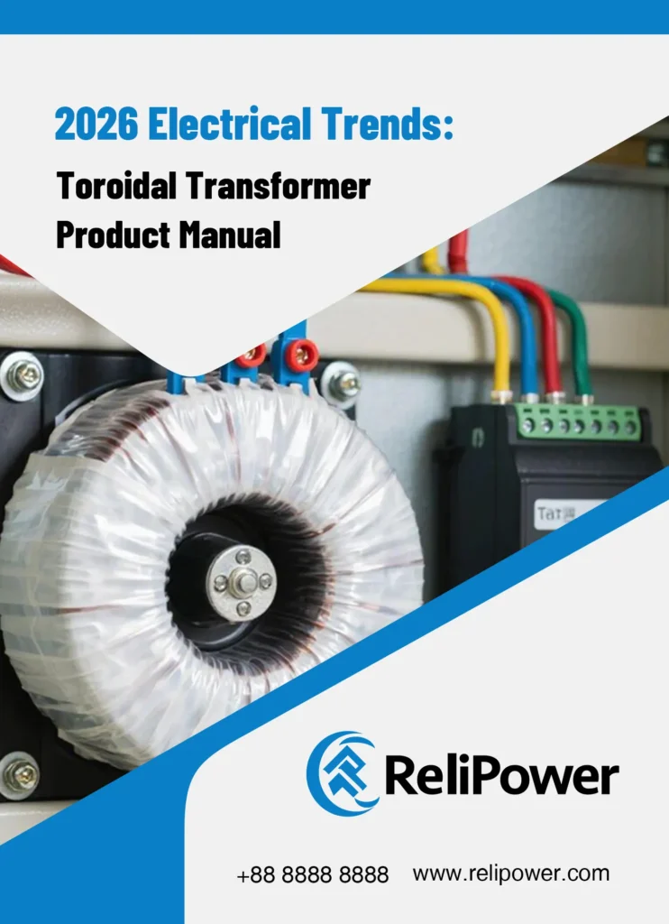
A toroidal transformer is a power transformer built around a donut-shaped (toroid) magnetic core, typically made from a continuous strip of grain-oriented silicon steel wound into a ring. The primary and secondary windings are wrapped uniformly around this ring core, with the magnetic flux path entirely contained within the core itself.
This geometry is fundamentally different from the more common EI (or shell-type) laminated transformer, which uses stacked E-shaped and I-shaped steel laminations to form a rectangular core. Both transformer types perform the same basic function — converting voltage and isolating circuits — but the toroidal geometry produces meaningfully different electrical and mechanical characteristics.
The core construction difference
In a toroidal, the silicon steel strip is wound in a continuous spiral to form the ring core. There are no air gaps, no joints, no lamination steps in the magnetic path. Magnetic flux travels around the ring with minimal losses or leakage outside the core. Quality toroidals achieve up to 97.5% stacking factor, meaning 97.5% of the core volume is active magnetic material rather than dead space.
In an EI transformer, the stacked E and I laminations create dozens of micro air gaps where the laminations meet. These air gaps generate magnetic flux leakage (EMI), mechanical vibration at the AC line frequency (audible hum), and lower magnetic efficiency. Typical EI stacking factor: 90-93%.
The toroidal’s continuous core is the source of every advantage I described above — lower EMI, lower audible noise, smaller size, higher efficiency.
The winding configuration
Toroidal windings wrap directly around the core, distributed evenly around the entire ring. Primary and secondary windings are typically layered, with insulation (typically Mylar tape and polyester film) between layers and a complete winding turn for every wrap around the core.
This uniform winding distribution contributes to the toroidal’s electrical advantages — better coupling between primary and secondary, lower leakage inductance, faster transient response under load changes.
Operating at higher flux density
Toroidal transformers operate at flux densities of 16-18 kilogauss, while traditional EI transformers operate at 12-14 kilogauss. The higher flux density is possible because the continuous core has no air gaps to limit flux carrying capacity. This is the primary reason why a toroidal can deliver the same VA rating in 50% less volume than an equivalent EI transformer.
How toroidals compare in practical applications
For most commercial 50-60 Hz power applications, toroidal vs EI selection comes down to whether you need the specific advantages a toroidal provides:
The cost premium is real, but the application-specific advantages are also real. For applications where EMI, noise, weight, efficiency, or compactness matter, toroidal is worth the premium. For general industrial step-down applications without these specific requirements, EI is often the right cost-effective choice.
Why are toroidal transformers better than EI laminated ones?
Toroidal transformers offer 6 key advantages over EI laminated equivalents: 8× lower magnetic field leakage (under 5 mG vs visible field at 5 cm), 6-10 dB lower audible operating noise, 50% smaller physical size and 50% lighter weight for the same VA rating, 3-7% higher operating efficiency, 10-15°C lower operating temperature at the same load, and lower no-load losses (under 2W for 50 VA toroidals vs 4-6W for equivalent EI). These advantages come with two tradeoffs — 30-50% higher manufacturing cost and 3-15× higher startup inrush current.
Advantage 1 — Dramatically lower EMI
Magnetic flux leakage from a transformer creates electromagnetic interference that affects nearby sensitive electronics. The toroidal’s continuous core contains nearly all magnetic flux within the core itself.
For audio amplifier manufacturers, this means a toroidal placed near sensitive amplifier circuitry creates almost no audible hum in the output. EI transformers in the same position create characteristic 60 Hz / 120 Hz buzz that’s audible in quiet listening environments.
For medical equipment with sensor circuits, the toroidal’s low EMI prevents measurement artifacts that an EI transformer would inject into nearby ADC inputs or precision analog circuitry. The toroidal’s typical 5 mG stray field at 5 cm distance is well below the threshold that disrupts precision instrumentation.
For EV charging stations, low EMI matters because charging circuits often share enclosures with communication electronics (network controllers, payment processors, monitoring sensors). EI transformer EMI interferes with these subsystems; toroidals don’t.
Advantage 2 — Quieter operation
EI transformers generate audible mechanical hum at 100-120 Hz (twice the AC line frequency) from lamination vibration in the air gaps. Even quality EI transformers buzz noticeably at higher loads.
Toroidal cores have no air gaps — the continuous strip core has nothing to vibrate at the AC frequency. Quality toroidals operate at near-silent levels even at full rated load.
For premium audio equipment, hospitality applications (hotel room equipment, restaurant POS systems), marine cabins (where shore-power transformers must run silently 24/7), and laboratory environments, this difference is operationally significant.
Advantage 3 — Smaller and lighter
Toroidal cores are more magnetic-efficient per kilogram of core material than EI laminations. The same VA rating fits into a smaller, lighter package.
For portable equipment (medical devices, portable audio amplifiers, mobile broadcast equipment), this is often the deciding factor — engineering teams need the smallest, lightest transformer that meets the specifications.
For marine applications, the weight savings have direct financial implications. A 3.6 kVA marine isolation toroidal at 20 kg replaces an EI equivalent weighing 40 kg — every kilogram saved on a boat translates to fuel efficiency and cargo capacity over the vessel’s operational life.
Advantage 4 — Higher efficiency and lower no-load losses
Toroidal transformers typically operate at 92-95% efficiency at rated load, versus 85-92% for EI laminated equivalents. The difference is 3-7 percentage points, which translates to less heat generation and lower energy costs over the equipment’s lifetime.
The no-load loss difference is even more pronounced. A 50 VA toroidal consumes under 2W in no-load condition; an equivalent 50 VA EI transformer consumes 4-6W just sitting idle. For always-on applications — UPS systems running 24/7, industrial control equipment, hospital equipment that never powers down — this no-load efficiency compounds dramatically over years of operation.
For a 200 VA always-on transformer, the no-load efficiency difference between toroidal and EI saves roughly 50-80 kWh per year per transformer. Across a building installation with hundreds of always-on transformers, the cumulative savings are real money.
Advantage 5 — Lower operating temperature
The combination of higher efficiency and continuous core construction means toroidals run 10-15°C cooler than equivalent EI transformers under the same load. Lower operating temperature directly translates to longer insulation life (every 10°C reduction roughly doubles insulation lifespan) and reduced cooling requirements in enclosed installations.
For installations in temperature-controlled environments (medical equipment cabinets, audio rack systems, sealed marine compartments), the lower heat output reduces HVAC load — a meaningful operational cost factor.
Advantage 6 — Better thermal management for enclosed applications
Toroidal geometry dissipates heat uniformly across the entire ring surface. EI transformers concentrate heat at the center of the lamination stack, creating thermal hot spots that limit power density.
For enclosed cabinets, sealed enclosures, and potted assemblies, the toroidal’s uniform thermal profile allows higher power density without local overheating. This is why marine isolation transformers (which must be sealed in epoxy resin for saltwater protection) are nearly always toroidal — the EI alternative would overheat in the same sealed package.
The two tradeoffs
Tradeoff 1 — Higher cost: Toroidal cores require specialized winding equipment that EI transformers don’t need. The continuous strip core is mechanically harder to wind than stacking laminations. Manufacturing cost is 30-50% higher than equivalent EI for the same VA rating.
Tradeoff 2 — Higher inrush current: When you switch a toroidal on, the initial magnetizing current can be 3-15× the rated operating current for the first 1-3 cycles of AC. This high inrush can trip standard circuit breakers and stress upstream components.
The inrush tradeoff requires engineering attention — slow-blow fuses, NTC (negative temperature coefficient) inrush limiting components, or soft-start circuits to manage initial current. For most applications this is a solved engineering problem, but it’s something to be aware of during system design.
What core materials are used in toroidal transformers?
Toroidal transformer cores are made from one of three magnetic materials, each with different performance and cost characteristics: grain-oriented silicon steel (the standard for 50-60 Hz power transformers, most common), amorphous metal alloy (premium choice for ultra-low losses), or nanocrystalline alloy (specialty material for high-frequency and ultra-high-efficiency applications). The material choice significantly affects efficiency, cost, and application suitability.
Silicon steel cores (grain-oriented, M4/M5/M6 grades)
The standard material for commercial toroidal transformers operating at 50-60 Hz power frequencies. Grain-oriented silicon steel comes in different grades distinguished by core loss characteristics:
- M4 grade — Highest performance, lowest core loss (typically 1.0-1.2 W/kg at 1.7 Tesla), most expensive. Used for premium audio, precision medical, and ultra-low-loss commercial applications.
- M5 grade — Mid-tier performance (typically 1.2-1.5 W/kg at 1.7 Tesla), balanced cost-performance. The most common material for commercial toroidals across general industrial, medical, and audio applications.
- M6 grade — Standard performance (typically 1.5-2.0 W/kg at 1.7 Tesla), most economical. Used for cost-sensitive commercial applications where premium efficiency isn’t critical.
For most B2B toroidal procurement, M5 silicon steel hits the sweet spot. Premium specialty applications (Hi-Fi audio, medical-grade isolation, EV charging where every percentage of efficiency matters) justify M4 grade. Cost-sensitive general industrial applications can use M6.
Amorphous metal alloy cores
Amorphous alloy has 70-80% lower core losses than M4 silicon steel — roughly 0.2-0.3 W/kg at the same operating point. The material is produced by rapidly cooling molten metal so that no crystalline structure forms, creating a non-crystalline (amorphous) structure with minimal magnetic domain boundaries.
Advantages:
- 70-80% lower no-load losses vs silicon steel
- Higher efficiency at low loads (matters for variable-load applications)
- Excellent magnetic permeability
Disadvantages:
- 40-60% higher core material cost
- More difficult to manufacture (specialized winding equipment required)
- Saturation flux density lower than silicon steel (limits peak performance)
Best fit: Always-on applications where no-load losses matter (UPS systems running 24/7, data center power, distributed power infrastructure), EV charging stations with continuous standby operation, premium audio applications with cost flexibility.
Nanocrystalline alloy cores
Nanocrystalline cores combine the best of crystalline and amorphous properties. They have grain sizes of 10-15 nanometers (essentially crystalline at the nanoscale), giving them very high permeability with low losses. Core losses can reach 0.1-0.2 W/kg, even lower than amorphous.
Advantages:
- Lowest core losses of any practical core material
- Excellent high-frequency performance (used in high-frequency converters)
- Very high saturation flux density (up to 1.2 Tesla)
- Compact size for given VA rating
Disadvantages:
- Highest cost of the three materials (typically 2-3× silicon steel cost)
- Manufacturing complexity limits volume production
- Application typically requires custom design
Best fit: High-frequency applications (EV fast charging at 20-100 kHz, switching power supplies, specialty industrial), compact medical equipment where size constraints dominate, military and aerospace applications.
How to choose the right core material
For 95% of standard 50-60 Hz commercial toroidal applications, M5 silicon steel is the right choice — it balances cost, performance, and availability. The other materials matter for specialized applications:
For B2B procurement, ask your manufacturer specifically which material grade they use. Quality manufacturers (including ReliPower) publish core material specifications openly on the datasheet. Manufacturers that hide this information typically use cheaper M6 or generic silicon steel without specific grain orientation.
What’s the difference between Class B, Class F, and Class H insulation?
Insulation class defines the maximum continuous operating temperature the transformer’s winding insulation can withstand. The three classes used in commercial toroidals — Class B (130°C), Class F (155°C), Class H (180°C) — directly determine where the transformer can operate reliably and how long it will last in service.
Class B insulation (130°C maximum)
Standard for commercial indoor applications operating in temperature-controlled environments (typical office, retail, commercial buildings at 25°C ambient). The 130°C maximum hot-spot temperature provides adequate margin for steady-state operation in normal conditions.
Best for:
- General commercial transformer applications
- Audio amplifiers in climate-controlled studios and homes
- Indoor commercial lighting
- Office and retail equipment
Typical service life at rated conditions: 15-20 years.
Class F insulation (155°C maximum)
The most common choice for premium commercial and industrial toroidals. The 25°C higher temperature rating provides better margin for elevated ambient conditions and overload tolerance.
Best for:
- Industrial automation and control panels
- Medical equipment (often required by IEC 60601 medical safety standards)
- Marine vessel applications (sealed enclosures with limited cooling)
- UPS systems with continuous operation
- EV charging stations with elevated ambient temperatures
Typical service life at rated conditions: 20-25 years.
Class H insulation (180°C maximum)
Premium specification for high-temperature industrial environments, traction motors, and severe-duty applications where ambient temperatures or thermal cycling could push winding temperatures beyond Class F limits.
Best for:
- Heavy industrial equipment in factory environments
- Outdoor utility applications
- Specialty traction and motor drive applications
- Some marine and offshore applications
- Mission-critical military and aerospace systems
Typical service life at rated conditions: 25-30+ years.
How insulation class affects service life
The relationship between operating temperature and insulation lifespan follows the Arrhenius equation — for every 10°C reduction below rated maximum, insulation lifespan approximately doubles. So a Class F transformer rated for 155°C maximum that actually operates at 130°C will last roughly 4× longer than the same insulation system at 155°C.
This is the practical reason why specifying margin matters. A Class F transformer used at Class B-level operating temperatures (130°C) effectively becomes a 60+ year service life component.
How to choose insulation class
For most commercial applications, Class F is the default choice — it provides adequate margin for typical operating conditions while remaining cost-effective. Class B is appropriate for cost-sensitive applications in mild environments. Class H is reserved for severe duty conditions.
For B2B procurement, specify insulation class based on:
- Maximum ambient temperature at the installation
- Expected loading factor (continuous full load vs intermittent)
- Thermal cycling characteristics (frequent on-off vs always-on)
- Service life expectations (15 years vs 30 years)
How do I size a toroidal transformer for my application?
Match the transformer’s VA (volt-amp) rating to your application’s actual power requirement, with appropriate headroom for inrush current, startup transients, and operating margin. For continuous-load applications, target 50-70% of rated VA capacity for long-term operation. For intermittent loads, slightly higher loading is acceptable. Standard sizing ranges from 50 VA (small instrument applications) to 5000 VA (industrial three-phase applications), with custom designs available up to 20,000 VA or larger.
The VA calculation formula
VA = output voltage × output current (per secondary winding)
For a transformer with multiple secondaries, sum the VA across all secondaries.
Example: An audio amplifier needs:
- ±35V DC rails for output stage
- ±15V DC rails for preamplifier
- +12V DC for control circuit
If the amplifier output stage draws 3A maximum on each rail, the ±35V secondary needs to deliver 105 VA per polarity = 210 VA total for the bipolar supply. The ±15V at 0.5A each = 15 VA total. The +12V at 1A = 12 VA.
Total transformer requirement: 210 + 15 + 12 = 237 VA, rounded up to 300 VA for headroom.
Headroom factors by application
For audio amplifiers and high-transient loads:
- 1.5-2× peak VA over continuous VA (audio loads have large peak current demands)
For continuous loads (medical, industrial, UPS, marine isolation):
- 1.3-1.4× rated VA over continuous load
For low-duty cycle applications:
- 1.2× rated VA may be sufficient
For applications with frequent on-off cycling:
- 1.5× or higher to manage inrush stress on the transformer windings
For EV fast charging applications:
- 1.5-2× rated VA to handle dynamic load changes during charging session
A practical example — 5000VA industrial UPS application
Consider a 5000VA UPS design for a small data center room:
- Continuous output: 3500W resistive (3500 VA at unity power factor)
- Server power factor correction: 800 VA reactive
- Battery charging during line operation: 500 VA
- Internal electronics: 100 VA
Total: 4900 VA continuous, with peaks up to 5500 VA during battery charging
Sizing analysis:
- Continuous VA: 4900
- Apply 1.4× headroom: 6860 VA
- Round up to standard size: 5000 VA toroidal transformer (top of standard catalog) or 6000 VA custom
For this application, a 5000VA Class F toroidal with amorphous core material provides:
- Continuous duty rating with margin
- Low no-load losses (matters for 24/7 operation)
- Class F insulation for elevated ambient in equipment room
- High efficiency (95%+) reducing UPS heat generation
A practical example — marine isolation transformer 3600VA
For a 3.6 kVA marine isolation transformer for a mid-size yacht:
- 30A continuous load at 120V = 3600 VA
- Galvanic isolation requirement (separates shore ground from hull ground)
- Saltwater environment requiring epoxy potting
- Operating temperature: -10°C to +50°C (marine enclosure ambient)
Sizing analysis:
- Rated continuous load: 3600 VA
- Marine duty headroom: 1.2× (continuous duty in stable load)
- Required: 4320 VA, round up to 4500 VA toroidal
For marine isolation, the transformer also needs:
- Class F insulation (sealed enclosure runs warmer)
- IEC 60092 compliance (marine electrical standard)
- UL Marine certification or equivalent classification society approval (ABS, DNV, LR, BV)
- Solid epoxy potting for saltwater resistance
- IEC 60601-1 medical-grade isolation (4 kV hi-pot test minimum)
What’s the difference between single-phase and three-phase toroidal transformers?
Single-phase toroidal transformers (the most common configuration) have one primary winding and one or more secondary windings, operating on standard single-phase 120V or 230V AC mains. Three-phase toroidal transformers have three primary windings connected to three-phase AC systems (typically 208V, 400V, or 480V), delivering higher power capacity in industrial applications where three-phase electrical service is available.
When single-phase is appropriate
For applications under 5000 VA in commercial buildings, audio equipment, medical devices, marine vessels, and residential equipment, single-phase toroidals cover the requirement. About 80% of toroidal transformer applications use single-phase configurations.
Single-phase advantages:
- Simpler primary connection (two wires plus ground)
- Standard for residential and commercial 120V/230V mains
- Lower cost for the same VA rating
- Easier installation and replacement
When three-phase becomes necessary
Three-phase toroidals are required when:
- Total power exceeds 5000 VA (single-phase becomes impractical at higher VA)
- The application connects to three-phase commercial or industrial service
- Balanced power distribution across three phases is needed (industrial loads)
- The downstream application requires three-phase output (motor drives, large machinery)
Three-phase advantages at high power:
- More efficient power transfer per copper weight
- Smaller transformer envelope for the same total VA
- Better matched to industrial three-phase loads
- Reduced harmonic distortion in many configurations
Three-phase configurations
Three primary configurations dominate three-phase toroidal applications:
- Delta-Delta (Δ-Δ) — Both primary and secondary in delta connection. Common for industrial step-down from 480V to 240V. No neutral connection on either side.
- Delta-Wye (Δ-Y) — Primary delta, secondary wye with neutral. Common for distribution transformers stepping down to 208V/120V building service. Provides neutral connection for single-phase loads.
- Wye-Wye (Y-Y) — Both primary and secondary in wye configuration. Less common for toroidals but used for specific applications requiring neutral on both sides.
For industrial applications, Delta-Wye is the most common configuration because it allows the same transformer to feed both three-phase loads and single-phase loads (using the wye neutral).
Three-phase sizing considerations
Total VA capacity for three-phase = √3 × line voltage × line current
For a 480V three-phase service feeding a 30 kVA load:
- Line current per phase = 30,000 / (√3 × 480) = 36.1 A per phase
- Each of the three windings carries 10 kVA
This makes a three-phase 30 kVA toroidal physically smaller than a single-phase 30 kVA toroidal (which would have to handle the full 36 A on one primary).
For industrial applications above 10 kVA, three-phase is almost always more cost-effective than single-phase.
Does the transformer need to handle 50Hz or 60Hz?
Yes, and getting this wrong damages the transformer. A transformer designed for 60Hz operation runs at 17% higher flux density when fed 50Hz at the same voltage, often pushing the core into magnetic saturation. The transformer overheats, draws excessive current, and fails within hours of operation.
The frequency-flux relationship
Magnetic flux in a transformer core is inversely proportional to frequency at constant voltage. Specifically:
Flux ∝ Voltage / Frequency
When you feed a 60Hz-designed transformer with 50Hz at the same voltage:
- Frequency drops 17% (60→50 Hz)
- Flux density rises 20% to compensate
- Core approaches or exceeds saturation
- Magnetizing current rises dramatically
- Transformer overheats
The reverse (50Hz transformer fed 60Hz) is safe — the lower flux density just means the transformer operates below its design point, with slightly reduced efficiency but no damage risk.
Universal frequency design
Most quality commercial toroidals are designed for “50/60Hz” operation, meaning they’re flux-rated for the lower 50Hz operating point. This means they work in any global market:
- North America (60Hz): operates at 83% of designed flux density (cooler, slightly less efficient)
- Europe, Asia, Australia (50Hz): operates at full designed flux density
For B2B export applications targeting multiple markets, always specify “50/60Hz” rated transformers. Avoid frequency-specific designs unless cost optimization for one market specifically justifies it.
Frequency considerations for specialty applications
For aviation and aerospace applications using 400Hz power systems, transformers must be specifically designed for that frequency. The high-frequency operation allows much smaller transformer envelopes for the same VA.
For EV fast charging using high-frequency power conversion (20-100 kHz), specialized high-frequency toroidal transformers with nanocrystalline cores are required — standard 50/60Hz silicon steel toroidals cannot operate at these frequencies.
What’s the difference between copper and aluminum windings?
Toroidal transformers can be wound with either copper wire (the traditional and premium choice) or aluminum wire (a cost reduction for lower-end transformers). Copper has 70% better conductivity than aluminum at the same gauge, which means smaller wire diameter for the same current capacity, less heat generation, and longer service life. Aluminum costs about 50% less per kilogram, which translates to 10-15% lower transformer cost — but with significant performance penalties.
Copper winding advantages
- Smaller wire diameter for same current = smaller transformer envelope
- Lower I²R losses = less heat generation = longer service life
- Better corrosion resistance over time
- Standard for premium audio, medical, marine, and industrial applications
- Higher overload tolerance during peak demand
Aluminum winding tradeoffs
- 50% lower wire cost translates to ~10-15% transformer cost reduction
- Larger wire diameter needed for same current = larger transformer envelope
- Higher I²R losses = more heat = faster aging of insulation
- More difficult to terminate (aluminum cold-flows under pressure)
- Not standard for premium audio, medical, or marine applications
When aluminum is acceptable
For cost-sensitive industrial applications (general HVAC equipment, basic control transformers, large power transformers in utility-scale projects), aluminum windings can be a legitimate cost optimization. The transformer is larger and runs hotter, but the application doesn’t care.
When copper is mandatory
For audio amplifier transformers, medical-grade isolation transformers, marine isolation transformers, EV charging applications, UPS systems, and any application where transformer efficiency or physical size matters, copper is the standard. Aluminum windings in these applications create downstream engineering problems that exceed the 10-15% material savings.
For commercial toroidal transformer specifications, copper is the default unless explicit cost optimization drives an aluminum decision.
What are the standard configurations for primary and secondary windings?
Primary and secondary windings can be configured in multiple ways depending on the application:
Single primary configurations
Most simple toroidals have a single primary winding designed for one AC input voltage (e.g., 120V AC or 230V AC). This is the most cost-effective configuration for fixed-voltage applications.
Dual primary for 120V/230V switching
For products shipping into multiple voltage markets, dual primary windings allow the same transformer to operate on either 120V or 230V depending on how the primaries are wired (parallel for 120V, series for 230V). This eliminates the need for separate transformers per market.
Multiple secondary configurations
Most applications need multiple voltage rails:
- Bipolar supplies for audio amplifiers (±35V from two secondary windings)
- Multiple isolated rails for medical equipment (separate secondaries for different circuit groups)
- Center-tapped secondaries for full-wave rectification
The transformer manufacturer can wind multiple secondaries on the same core, each with its own voltage and current rating.
Center-tapped secondaries
A center-tapped secondary provides three connection points — two outer terminals and one center tap. Used commonly for:
- Bipolar rectifier circuits (extracting ±V from one secondary)
- Audio amplifier supplies needing balanced power rails
The center tap location is precisely defined during transformer design.
Foil vs wire winding
For lower-power transformers (under 200 VA), copper wire winding is standard. For higher-power toroidals (over 500 VA) where layer-to-layer capacitance matters, some manufacturers use copper foil winding instead. Foil-wound toroidals provide better voltage regulation and lower stray capacitance, but at additional cost.
For most commercial applications, wire winding is the standard. Foil winding is specified for high-end audio amplifiers and precision instrumentation applications.
Why is epoxy potting important for toroidal transformers?
Epoxy potting (encapsulating the transformer in solid epoxy resin) provides three critical engineering advantages for specific applications: complete moisture sealing for marine and outdoor environments, vibration resistance for transportation and industrial applications, and electrical safety isolation for medical and patient-connected equipment. For these applications, epoxy potting is often required by safety standards.
Marine epoxy potting
Marine isolation transformers must operate in saltwater spray environments where conventional transformer enclosures would corrode within months. Solid epoxy potting completely seals the transformer windings and core, with the entire assembly housed in a non-metallic enclosure.
The epoxy potting provides:
- Complete saltwater barrier (no moisture ingress over years of service)
- Galvanic isolation (no metal-to-metal contact with vessel hull)
- Vibration resistance (continuous wave motion at sea)
- Electrical safety isolation (UL Marine listing and IEC 60601 medical-grade dielectric)
For marine isolation transformers, epoxy potting is essentially required. Conventional open-frame or varnish-impregnated construction fails within 12-24 months of saltwater exposure.
Industrial vibration applications
Transformers in industrial equipment subject to continuous vibration (rotating machinery, mobile equipment, vehicle-mounted systems) experience winding insulation stress over time. Epoxy potting eliminates vibration-induced winding movement by mechanically locking all windings in place.
For rail traction transformers, mobile broadcasting equipment, EV charging stations in earthquake zones, and similar applications, epoxy potting extends service life significantly.
Medical isolation potting
Medical isolation transformers per IEC 60601-1 must withstand 4 kV hi-pot dielectric tests and limit leakage current to 100-300 microamperes depending on application classification. Epoxy potting provides the dielectric reinforcement needed to consistently meet these requirements.
For patient-connected medical equipment (operating rooms, ICU, anesthesia systems), epoxy-potted medical isolation transformers are required by safety standards.
When epoxy potting isn’t needed
For indoor commercial applications (audio amplifiers, office equipment, industrial control panels with normal vibration), conventional varnish impregnation provides adequate moisture and vibration protection at much lower cost. Epoxy potting is reserved for specifically demanding applications.
For most commercial toroidal transformers, varnish impregnation with high-quality polyester or polyurethane varnish is the standard. Epoxy potting adds 25-40% to transformer cost and is specified only when the application requires it.
How much does a custom toroidal transformer cost?
Custom toroidal transformer pricing depends heavily on VA rating, core material, copper vs aluminum winding, number of secondary windings, certification requirements, and order volume. For typical 2026 market rates from established Chinese manufacturers, expect roughly $8-15 per VA at 50-unit MOQ, dropping to $4-8 per VA at 1,000+ unit volumes.
Cost factors
Several factors drive toroidal transformer cost:
VA rating — Larger transformers need more core material and copper. The cost per VA decreases as VA increases (a 1000 VA transformer costs less per VA than a 100 VA transformer).
Core material — Standard M5 silicon steel is baseline. M4 grade adds 10-15%. Amorphous alloy adds 40-60%. Nanocrystalline adds 100-200%.
Copper vs aluminum — Aluminum saves 10-15% on transformer cost but adds engineering complications. Copper is standard for quality work.
Insulation class — Class B baseline. Class F adds 5-10%. Class H adds 15-25%.
Number of secondaries — Each additional secondary winding adds ~$1-2 per transformer for design and labor.
Certifications — UL, VDE, CE certifications add $0.30-0.80 per transformer at production cost.
Epoxy potting — Adds 25-40% over standard varnish impregnation, but required for marine and patient-connected medical applications.
Tolerance and binning — Precision tolerance windings (used for audio matching pairs) add 5-15% over standard tolerance.
Manufacturing volume — 50-unit MOQ pricing is roughly 1.5-2× the 1,000-unit volume pricing for the same design.
Typical 2026 market prices
For factory-direct from a quality Chinese manufacturer at 100-unit MOQ:
- 100 VA toroidal, M5 silicon steel, single primary, dual secondaries: $12-18 per unit
- 300 VA toroidal, M5 silicon steel, dual primary, audio configuration: $28-42 per unit
- 500 VA toroidal, M5 silicon steel, medical-grade with VDE certification: $45-70 per unit
- 1000 VA toroidal, M5 silicon steel, UPS-grade with thermal protection: $70-110 per unit
- 2000 VA toroidal, M5 silicon steel, industrial application: $130-200 per unit
- 3600 VA toroidal, M5 silicon steel, marine isolation with epoxy potting: $280-420 per unit
- 5000 VA toroidal, M4 silicon steel, three-phase industrial: $380-580 per unit
For premium specifications (amorphous core, IEC 60601 medical certification, marine isolation with classification society approval), expect 1.5-2.5× these prices.
For US/EU distributor channel, these prices typically double or triple. Suitable for prototype and very low volume work; not cost-effective for OEM production.
For factory-direct at 1000+ unit volumes, expect 30-50% lower per-unit pricing than the 100-unit pricing above.
What certifications do toroidal transformers need?
Certification requirements depend on the target market and application. For general commercial sales in major markets:
UL/CSA for North America
UL 506 (Specialty Transformers) is the primary US certification for toroidal transformers. CSA C22.2 No. 66 covers Canada. Most quality toroidal manufacturers carry combined cUL Listing covering both US and Canada.
For medical applications, UL 60601-1 medical electrical equipment standards apply, including requirements for medical-grade isolation transformers.
For marine applications, UL Marine certification (separate listing for boat and vessel use) is required.
CE/VDE for Europe
CE marking under the EU Low Voltage Directive is required for European sales. VDE certification provides additional German market acceptance and is widely recognized across Europe.
For medical European applications, EN 60601-1 medical electrical equipment standards apply.
For marine European applications, IEC 60092 (Electrical Installations in Ships) is the cornerstone international standard.
Classification society approvals for marine
For commercial marine vessels, isolation transformers must carry approvals from one of the major classification societies: ABS (American Bureau of Shipping), DNV (Det Norske Veritas), Lloyd’s Register (LR), Bureau Veritas (BV), CCS (China Classification Society), or RINA (Italian Naval Register). Each society conducts its own approval process for transformer designs intended for shipboard use.
CCC for China
China Compulsory Certification (CCC) is required for many transformer types sold within China. Important for OEMs distributing equipment in Chinese domestic market.
Other major market certifications
- PSE — Japan (Product Safety Electrical Appliance certification)
- SAA / RCM — Australia and New Zealand
- INMETRO — Brazil
- ENEC — Pan-European endorsement
For products targeting global commercial sales, sourcing transformers with combined certification (UL + CE + CCC + PSE) on a single product file simplifies multi-market deployment.
How do I specify a custom toroidal transformer to a supplier?
A complete custom toroidal specification includes 14 critical parameters that the supplier needs to design and manufacture your transformer. Missing any of these leads to back-and-forth and missed lead times.
Specification checklist
- VA rating — Total power capacity needed, with headroom factor applied
- Primary voltage — Single (120V or 230V) or dual primary configuration; specify the voltage range (e.g., 110-240V universal)
- Phase configuration — Single-phase or three-phase; if three-phase, specify connection type (Delta-Delta, Delta-Wye, Wye-Wye)
- Operating frequency — 50/60Hz universal, 50Hz only, 60Hz only, or specialty (400Hz aviation)
- Secondary voltage(s) and current(s) — Each secondary winding’s voltage and current rating
- Number of secondaries — How many independent winding outputs needed
- Center-tapped or single-ended — Whether secondaries need a center tap
- Insulation class — Class B (130°C), Class F (155°C), Class H (180°C)
- Core material grade — M4/M5/M6 silicon steel, amorphous alloy, nanocrystalline (default M5)
- Winding material — Copper (default) or aluminum (cost optimization)
- Encapsulation type — Open frame, varnish impregnated, vacuum potted, epoxy potted
- Mounting method — Center bolt mounting, vertical mounting bracket, custom enclosure
- Certification requirements — UL, CSA, CE, VDE, CCC, PSE, classification societies
- Operating environment — Maximum ambient temperature, vibration class, humidity, salt spray exposure
Beyond these basics, optional specifications:
- Leakage current limit — Particularly important for medical (under 300 μA) and marine isolation
- Hi-pot dielectric test voltage — Standard 2 kV vs medical-grade 4 kV
- Lead wire length and termination — Standard 200mm lead vs custom length, terminal type
- Acoustic noise requirement — Standard <30 dBA vs ultra-quiet <20 dBA
- Thermal cutout or fuse — Integrated thermal protection
- Logo and branding — OEM/wholesale custom labeling
A complete specification document including all these parameters lets the manufacturer respond with accurate quote and lead time within 24-48 hours. Incomplete specifications create cycles of clarification questions that delay quotes by 1-2 weeks.
How do I install a toroidal transformer safely?
Toroidal transformers have specific installation considerations beyond standard EI transformer practice:
Inrush current management
Toroidal startup current can be 3-15× the rated operating current for the first 1-3 cycles. Standard fast-blow fuses or breakers will trip on this inrush.
Solutions:
- Slow-blow fuses sized at 1.5-2× the rated current
- NTC thermistors in series with the primary for inrush limiting (best for under 500 VA)
- Active soft-start circuits using SCR or relay-based current limiting (best for over 500 VA)
- Inrush current limiters built into the transformer enclosure for plug-and-play applications
For UPS, audio amplifier, and EV charging applications, soft-start circuits are typically integrated into the equipment design.
Mounting orientation
Toroidal transformers can typically be mounted in any orientation — horizontal, vertical, or even inverted. The continuous core has no preferred orientation for performance.
The center bolt mounting (typically a single bolt through the toroidal center, with rubber or neoprene washers) is the standard approach for commercial toroidals. The mounting bolt MUST be insulated where it passes through the core to prevent creating a single-turn short-circuit winding. Use a non-conductive bushing or sleeve in the center bolt hole. This is critical — a conductive bolt through the toroidal center can burn out the transformer within seconds of power-up.
For DIN-rail installations (industrial control panel applications), specific DIN-rail mounting brackets are available. Confirm the mounting orientation with the manufacturer for DIN-rail integrated toroidals.
Ventilation and heat dissipation
Toroidals dissipate heat across their entire ring surface. They don’t need active cooling for most applications, but proper airflow around the transformer extends service life.
For enclosed installations (in equipment cabinets), ensure adequate ventilation — minimum 50mm clearance around the transformer is the typical recommendation. Operating temperature should stay below the insulation class rating — Class B insulation rated for 130°C maximum hot-spot temperature, Class F for 155°C, Class H for 180°C.
EMI considerations
Even though toroidals have very low EMI (under 5 mG at 5 cm distance), sensitive analog circuitry should be physically separated by at least 100-150mm from the transformer to maintain measurement accuracy.
For audio equipment, position the transformer perpendicular to amplifier circuitry to minimize residual flux coupling.
Grounding requirements
Proper grounding is essential for safety and EMC compliance. The transformer enclosure (for enclosed types) and the protective earth conductor on three-prong outlets must be connected to safety ground. For marine and medical applications, specific grounding schemes per IEC 60092 (marine) and IEC 60601-1 (medical) apply.
What applications use toroidal transformers?
Toroidal transformers excel in 8 application categories where their specific advantages — low EMI, quiet operation, compact size, high efficiency, low no-load loss — justify the cost premium over EI laminated equivalents.
Audio amplifiers
Audio amplifier manufacturers consistently choose toroidals over EI for the dramatic noise floor improvement. A toroidal placed near sensitive amplifier circuits creates minimal interference compared to an EI transformer. For premium audio and audiophile equipment, toroidals are essentially standard.
For tube amplifiers specifically, the low magnetic field leakage is critical to preserving the dynamic range and detail that tube circuits offer.
Medical electrical equipment
Medical-grade toroidal transformers are required for life-safety isolation between patient-connected equipment and AC mains. UL 60601-1 / EN 60601-1 standards govern medical isolation, with specific requirements for leakage current (under 100-300 μA depending on application), isolation voltage (4 kV minimum hi-pot), and creepage distances.
Toroidal geometry helps meet these requirements with better physical isolation between primary and secondary than EI transformer construction provides. The compact size also matters for portable medical equipment.
Marine isolation transformers
Marine isolation transformers are essentially required for boats connecting to shore power. They prevent galvanic corrosion of underwater metal components (propellers, shafts, hulls), eliminate stray AC currents that could cause electrocution in marina waters, and isolate ship grounding from shore grounding.
Marine isolation toroidals are typically:
- 3.6 kVA to 25 kVA depending on vessel size
- Solid epoxy potted in non-metallic enclosures
- UL Marine certified plus IEC 60601 medical-grade isolation
- Compliant with IEC 60092 (Electrical Installations in Ships)
- Approved by classification societies (ABS, DNV, LR, BV, CCS)
The toroidal’s compact size and weight savings are particularly valuable on boats where every kilogram affects fuel economy.
UPS and backup power systems
Online UPS systems (true double-conversion UPS) use toroidal transformers for the inverter output stage to provide clean sinusoidal output for sensitive equipment. The high efficiency reduces UPS energy losses during normal operation. The low no-load loss is particularly important for UPS systems that operate 24/7 — even small efficiency improvements compound into significant energy savings over the equipment’s 10-15 year service life.
Larger UPS systems (5000+ VA) often use toroidals for both the inverter output and the bypass transformer. Three-phase UPS systems use three-phase toroidal configurations.
EV charging stations
Electric vehicle charging stations increasingly specify toroidal transformers for several reasons:
For Level 2 AC charging (residential and commercial), toroidals provide isolation between the charging circuit and the utility grid, with compact form factor fitting within the charging station enclosure.
For DC fast charging (50-350 kW commercial fast chargers), high-frequency toroidal transformers with nanocrystalline cores convert utility AC to high-frequency DC. Recent research on 12-phase toroidal transformers shows efficiency improvements and reduced harmonic distortion for EV fast charging — a growing area of toroidal application.
The low EMI matters because EV charging stations include communication electronics (network controllers, payment systems, monitoring sensors) that share enclosures with the transformer. The low no-load loss is critical for charging stations with extended standby periods.
Industrial automation and control panels
Industrial control transformers for PLCs, motor drives, robotics, and process control benefit from toroidal characteristics — particularly the compact size that allows installation in space-constrained control panels, and the low EMI that prevents interference with adjacent sensors and control electronics.
For three-phase industrial applications above 5 kVA, three-phase toroidal configurations are increasingly competitive with conventional three-phase EI transformers.
Laboratory and instrumentation
Precision laboratory equipment (scientific instruments, calibrators, measurement systems) uses toroidals for EMI minimization to maintain measurement accuracy. The compact size also matters for benchtop instrumentation where rack space is premium.
Power transmission and distribution
Step-down transformers from medium voltage (typically 6-15 kV) to low voltage (208-480V) increasingly use toroidal designs for distribution applications where compactness, efficiency, and quiet operation matter. The toroidal’s higher efficiency reduces transmission losses, supporting grid reliability and energy cost savings.
How long do toroidal transformers last?
Quality copper-wound toroidal transformers from established manufacturers last 20-30 years in typical commercial operation. Premium medical-grade and audio-grade toroidals can reach 30-40 year service life with minimal degradation in performance. The longevity comes from the fundamentally robust core construction (no air gaps to degrade) and the inherent thermal margin from operating below insulation class limits.
Lifespan factors
Several factors determine actual service life:
Operating temperature — Insulation aging is the primary failure mechanism. Operating below the insulation class temperature rating dramatically extends life. Class F insulation at 130°C operating temperature lasts roughly 4× longer than the same insulation at 155°C operating temperature.
Loading factor — Operating at 50-70% of rated VA significantly extends life compared to operating at 90-100%. Heat generation scales with loading squared, so reducing load to 70% cuts heat by half.
Power quality — Continuous exposure to voltage transients, harmonics, and unbalanced loads stresses transformer insulation over years. Quality power conditioning extends transformer life.
Manufacturing quality — Quality varnish impregnation, proper layer insulation, certified component sourcing, and 48-hour aging tests during manufacturing all contribute to multi-decade service life.
When transformers need replacement
Toroidal transformers rarely fail catastrophically — they typically show gradual degradation:
- Increasing operating temperature at the same load
- Audible buzzing developing in previously silent units (sign of varnish degradation)
- Reduced output voltage regulation
- Smoke or burning smell (immediate replacement required)
For mission-critical equipment, planned replacement at 25-30 years is more cost-effective than reactive replacement after failure.
Common toroidal transformer specification mistakes
Six mistakes that account for most warranty issues and project delays:
Mistake 1 — Undersizing the VA rating
The most expensive mistake. Engineer calculates load requirements at nominal operating conditions but forgets to include peaks, inrush, and headroom. Transformer operates above 100% rated capacity, runs hot, and ages prematurely.
Fix: Always apply 30-50% headroom factor over calculated load requirements. For audio applications, 100%+ headroom for peak transients.
Mistake 2 — Forgetting inrush current management
Engineer designs equipment with a standard fast-blow fuse, transformer trips the fuse on startup, and the production team scrambles to add inrush limiting.
Fix: Plan inrush limiting from initial design phase. NTC thermistors, slow-blow fuses, or soft-start circuits depending on VA rating.
Mistake 3 — Wrong insulation class for operating environment
Equipment installed in environments warmer than the insulation class allows. Transformer fails within 3-5 years instead of expected 20+ years.
Fix: Specify insulation class with margin for actual operating conditions. Class F for typical commercial; Class H for high-temperature or industrial.
Mistake 4 — Wrong core material for application
OEM specifies M6 silicon steel for an always-on UPS application where amorphous alloy would have paid back the 40-60% material premium in energy savings within 18-24 months.
Fix: Match core material to application duty cycle. For always-on applications with continuous operation, amorphous alloy often delivers better TCO than cheaper silicon steel.
Mistake 5 — Mounting bolt creating shorted turn
Conductive mounting bolt passes through transformer center without insulation, creating an unintended single-turn shorted winding that causes severe overheating within seconds.
Fix: Always use insulating bushings in the center mounting hole. Most quality toroidals include this in standard packaging.
Mistake 6 — Frequency mismatch between specification and operating market
OEM specifies 60Hz transformer for North American market but the product gets exported to Europe where 50Hz mains overdrive the core into saturation, causing failures within hours of operation.
Fix: For export-oriented OEMs, always specify 50/60Hz universal frequency rating. The cost premium is minimal; the protection against market mismatch is significant.
Where to source custom toroidal transformers
Three real sourcing channels.
Online marketplaces are fast but spec verification is unreliable. Custom toroidals require precise winding specifications; generic marketplace sourcing rarely delivers quality consistent with engineering requirements.
US/EU distributors carry standard catalog toroidal transformers from established brands at 2-3× factory direct pricing. Suitable for prototype and very low volume work; custom specifications generally not available through distributor channel.
Factory-direct from quality Chinese or Taiwanese manufacturers is the only channel that delivers custom toroidal designs at reasonable volumes. Established manufacturers offer 50-unit MOQ for custom designs, full certification support (UL, CE, VDE, CCC, classification societies), and 2-3 week sample turnaround.
That’s where we come in. ReliPower manufactures custom toroidal transformers in our Ningbo factory across the full commercial range: 15 VA to 5000 VA standard catalog (custom up to 20,000+ VA), single-phase and three-phase configurations, M4/M5/M6 silicon steel cores plus amorphous and nanocrystalline options for specialty applications, copper or aluminum windings, Class B/F/H insulation, open frame/varnish impregnated/vacuum potted/solid epoxy potted construction options. Full UL 506 + UL 60601-1 + CE + VDE + CCC + classification society certifications available. 50-unit MOQ for custom designs. Samples in 2-3 weeks. Send us your VA requirements, voltage configurations, target market certifications, and operating environment specs — we’ll respond with a complete quote within 24-48 hours.
FAQs
Why are toroidal transformers more expensive than EI transformers?
Toroidal cores require specialized winding equipment and more complex manufacturing process than stacking EI laminations. The 30-50% cost premium reflects actual manufacturing complexity, not arbitrary markup. For applications where the toroidal’s specific advantages (low EMI, quiet operation, compact size, low no-load loss) matter, the premium is engineering value, not waste.
What’s the difference between M4, M5, and M6 silicon steel cores?
The grade number indicates core loss characteristics. M4 has the lowest core loss (1.0-1.2 W/kg at 1.7 Tesla, highest cost), M5 is the most common mid-tier choice (1.2-1.5 W/kg, balanced cost-performance), M6 is the most economical (1.5-2.0 W/kg, used for cost-sensitive applications). For most commercial toroidals, M5 is the standard.
Should I use amorphous or silicon steel core for my application?
For always-on applications operating 24/7 (UPS systems, EV charging standby, data center equipment), amorphous alloy’s 70-80% lower no-load loss often pays back the 40-60% material cost premium within 18-24 months. For variable-load applications (audio amplifiers, intermittent industrial use), M5 silicon steel is the more cost-effective choice.
Do toroidal transformers buzz?
Properly designed and manufactured toroidal transformers should not produce audible buzz. If a toroidal develops buzzing over time, it usually indicates winding insulation degradation, varnish migration, or loose mechanical mounting. EI transformers naturally produce 100-120 Hz buzz from lamination vibration; toroidals do not.
How long do toroidal transformers last?
Quality copper-wound toroidals last 20-30 years in typical commercial operation. Premium medical-grade, marine, and audio-grade units reach 30-40 years. The primary aging mechanism is insulation degradation from heat exposure over years.
What’s the largest toroidal transformer available?
Standard catalog toroidal transformers reach 5000 VA single-unit capacity. Custom designs are routinely manufactured up to 20,000 VA for industrial and marine applications. For larger capacity, three-phase toroidal configurations or paralleled single-phase units provide higher total capacity.
Can I parallel multiple toroidal transformers for more capacity?
Yes, but the transformers must be matched in voltage ratio, internal impedance, and phasing. Parallel operation of mismatched transformers causes circulating currents that reduce efficiency and stress windings. For commercial applications, source a single larger transformer rather than paralleling smaller ones.
What’s the difference between Class B, F, and H insulation?
Class B insulation withstands 130°C continuous hot-spot temperature. Class F handles 155°C. Class H handles 180°C. Each 25°C step up in class rating provides additional thermal margin for elevated ambient temperatures or higher loading factors. For typical commercial applications, Class F is the default.
Why are marine isolation transformers always toroidal?
Three reasons: marine isolation requires complete saltwater protection via solid epoxy potting (toroidal geometry handles thermal dissipation better in sealed packages), marine applications need maximum power-to-weight ratio (toroidals are 50% lighter than EI equivalents), and marine vessels operate continuously requiring high efficiency (toroidals at 92-95% vs EI at 85-92%).
How do I tell if my toroidal transformer is failing?
Signs of impending failure: rising operating temperature at the same load, audible buzzing in previously silent unit, reduced output voltage under load, intermittent operation, smoke or burning smell. Smoke or smell requires immediate shutdown and replacement.
Should I use copper or aluminum windings?
For premium audio, medical, marine, EV charging, instrumentation, and UPS applications, copper is standard. Aluminum saves 10-15% on transformer cost but adds engineering complications (larger size, higher heat) that exceed the savings for most applications. Specify copper unless cost optimization specifically demands aluminum.
Can the same toroidal transformer work on both 50Hz and 60Hz?
Yes, if it’s specifically rated as “50/60Hz universal.” A transformer designed only for 60Hz cannot safely operate on 50Hz without risking saturation and overheating. For export-oriented OEMs targeting multiple global markets, always specify 50/60Hz universal frequency rating.
Related guides
- LED Power Supply: The Complete Buyer’s Guide for OEMs and Contractors Foundation guide on LED-specific power supplies; companion to this toroidal transformer guide.
- Toroidal Transformer vs EI Laminated: Side-by-Side Comparison Detailed comparison of the two transformer types with specific decision factors.
- Toroidal Transformer for Audio Amplifiers: Why Audiophiles Choose Them Deep dive on the most common toroidal application — premium audio amplifiers.
- Toroidal Transformer Inrush Current: Causes and Solutions Engineering solutions for managing toroidal startup current.
- How to Calculate VA Rating for a Toroidal Transformer Detailed sizing calculations for different application types including 5000VA industrial.
- Toroidal Core Materials: Silicon Steel vs Amorphous vs Nanocrystalline Detailed core material decision framework for different application types.
- Marine Isolation Transformer: Toroidal Selection for Boats and Vessels Marine-specific application guide including IEC 60092 and classification society approvals.
- Toroidal Transformer for EV Charging Stations EV charging application guide including high-frequency and DC fast charging.
- Medical-Grade Toroidal Transformer: IEC 60601 Compliance Guide Medical isolation transformer specifications including 4 kV hi-pot and 300 μA leakage current.
- Custom Toroidal Transformer: The Specs You Need to Send Your Supplier Complete specification framework for sourcing custom designs.
References and further reading
- UL 506 — Standard for Specialty Transformers, the primary US safety standard for toroidal transformer applications.
- UL 60601-1 — Medical Electrical Equipment Safety Standard, including requirements for medical isolation transformers.
- CSA C22.2 No. 66 — Standard for Specialty Transformers, the Canadian counterpart to UL 506.
- IEC 60076 — Power transformers, the international standard governing power transformer design and testing.
- IEC 60092 — Electrical Installations in Ships, the cornerstone international standard for marine electrical systems including isolation transformers.
- IEC 61558 — Safety of transformers, reactors, power supply units and combinations thereof.
- IEC 60601-1 — Medical Electrical Equipment Safety Standard, including requirements for medical-grade isolation transformers and patient leakage current limits.
- IEEE C57.110 — IEEE Recommended Practice for Establishing Liquid-Filled and Dry-Type Power and Distribution Transformer Capability When Supplying Nonsinusoidal Load Currents.
- VDE 0570 — German national transformer safety standard, widely recognized across Europe.
- Audio Engineering Society (AES) — Industry resources on transformer specifications for audio equipment.
- ABS (American Bureau of Shipping) — Marine classification society approval standards for shipboard electrical equipment.
- DNV (Det Norske Veritas) — Marine classification society standards for vessel electrical systems.